Axis Rotation and Axis Tilt Explained
Date Posted:
December 16, 2011
Category:
Bowling Technical Information
In this article, we will provide some information on axis
rotation angle and axis tilt angle, the two parameters that describe the
direction of the bowling ball’s rotation as it travels down the lane. Based on
discussions with many bowlers and as evidenced by many bowling internet forum
posts, we feel that these are often misunderstood (and sometimes incorrectly
interchanged) parameters and we hope to clear up some of this confusion so
bowlers can better understand their games and make better decisions, both on the
lanes and in the pro shop.
Basic Definitions
Bowling balls are spheres (at least externally) and they rotate. A rotating
sphere (and, in fact, any rotating object) can rotate about any axis passing
through its center of gravity. This is where the parameters of axis rotation
angle and axis tilt angle come in. They together uniquely describe which axis
 the ball is rotating about relative to both the lane and the ball’s direction of
travel. We’ll explain why this is important in a future article. For now, let’s look at
some images that will help us understand these two parameters a bit more
clearly. (Note: All images shown in this article are for right-handed bowlers.)
the ball is rotating about relative to both the lane and the ball’s direction of
travel. We’ll explain why this is important in a future article. For now, let’s look at
some images that will help us understand these two parameters a bit more
clearly. (Note: All images shown in this article are for right-handed bowlers.)
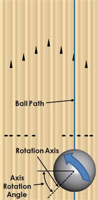
Shown to the right is a top view of a bowling ball on a lane, just after the
release (please note that this image is not to scale). In this image, the
blue line denotes the ball's path and its direction of travel. The large blue
arrow represents the ball's rotation. The black horizontal
line is perpendicular to the ball's direction of travel. The dotted line
represents the ball's axis of rotation (the axis about which the ball is
rotating). The axis rotation angle is the angle between the horizontal line and the dotted axis of rotation line.
So, in this example, the ball's axis rotation angle is somewhere in the vicinity
of 30-40 degrees.
Axis rotation angle, quite simply, is a measure of the amount of "side roll" the
ball has. A ball with no side roll has 0 degrees of axis rotation. A
ball with maximum side roll has 90 degrees of axis rotation.
Now, let's consider axis tilt angle. To explain tilt, we'll use an image
from a different angle: directly behind the ball, looking down the lane,
and aligned with its direction of travel. This is shown below.
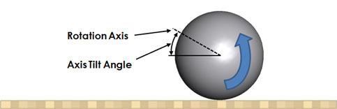
In this view, the blue arrow again represents the ball's direction of rotation.
The black horizontal line is parallel to the lane surface. The dotted line
again represents the ball's axis of rotation. The axis tilt angle
is the angle between the horizontal line and the dotted axis of rotation line.
In this example, the axis tilt angle is approximately 20-30 degrees.
Axis tilt angle, then, is a measure of the degree to which a ball is spinning.
A ball spinning like a top (and hence, rotating about a purely vertical axis of
rotation) has 90 degrees of axis tilt. A ball with no spin whatsoever
(having a purely horizontal axis of rotation) has 0 degrees of axis tilt.
How to Calculate Axis Rotation and Axis Tilt Graphically
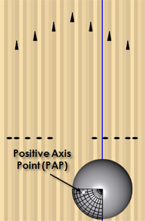
With a properly-positioned video camera, it is possible to determine a ball's
axis rotation and axis tilt angles from a single video shot. The first step of this
process is to mark the ball's positive axis point (PAP). The PAP is the
point on the ball intersecting its axis of rotation at release. When the PAP is
marked properly on the ball (often with a small, white, round piece of tape),
the mark will be completely stable as the ball is released (that is, the ball
will be rotating about
the mark). You can determine the approximate
location of the PAP by tracing the ball's initial oil ring. We won't
explain that process here, as there are already good online resources available
describing this (for example, click here).
As a side note, you may have noticed that we used the term "approximate" above.
Without getting too off-topic, it is important to remember that a high flaring
bowling ball starts flaring immediately when it is released. Therefore,
the first oil ring is not technically representative of the true PAP, as it
instead gives you the average rotation axis for the first revolution in which
the ball is in contact with the oiled lane. In most cases, this is close
enough for practical purposes, but for better accuracy, you would need to
manually adjust the originally-marked PAP location using slow-motion video until
the marked position is perfectly stable just as the fingers are leaving the
ball.
Getting back on topic, the next step of this process is to properly position the
video camera so that errors are not introduced. To minimize perspective
and alignment errors, the
camera should be positioned behind the bowler, aligned with the ball's direction
of travel, near lane level. (Note: A good bowling coach can be invaluable in
helping a bowler capture correct video footage, so we highly recommend that you
seek one out if you desire assistance with this process.)
Now, by capturing a video of the ball as it is thrown and extracting a frame from
the video just as the fingers are leaving the ball, we can compute axis rotation
and axis tilt angle graphically. This is done by utilizing an overlay
graphic, as shown below:
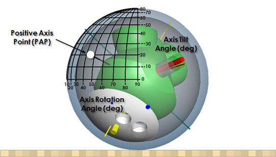
First, let's explain the overlay (containing all the black lines). The black
lines represent a parameterization of the ball's surface using a spherical coordinate system.
In a spherical coordinate system, any point on the surface of the sphere can be
represented by two angles. In this bowling-specific representation, the
two angles are axis rotation angle and axis tilt angle. Much like
longitude and latitude describe a point on the earth's surface, axis rotation
angle and axis tilt angle describe a point on the bowling ball's surface and
that point
represents its axis of rotation, measured with reference to its direction of travel.
In the above example, the PAP (marked with the white circle) tells us that the
ball has about 45 degrees of axis rotation and about 20 degrees of axis tilt.
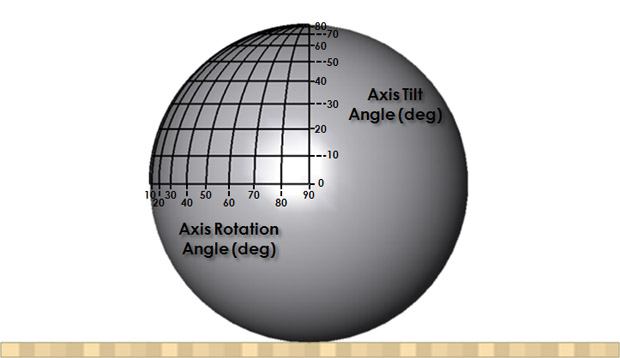
One thing worth mentioning is that this overlay method utilizes a 2D projection
of a 3D object. For this reason, the spacing between the lines is not
equal. For example, the linear distance in the overlay between 10 degrees
and 20 degrees is drastically different than the linear distance between 80
degrees and 90 degrees. We mention this only as a caution and to remind
you that half-way between 0 and 90 on the overlay is not 45.
Below is a slightly larger, less crowded version of the above overlay image, for
reference:
Closing Thoughts
While the above-described graphical analysis process is extremely useful and we'd love to take the credit for devising it, we
unfortunately cannot. Several versions of the rotation/tilt overlay graphic pre-date
this article, including, for example, this one and
this one.
One reason we mention these alternate overlay images is that we are confident
that astute readers will notice that the lines in our overlay graphic do not
align perfectly with the lines in either of the previously referenced images
(which, by the way, do not align perfectly with each other). Since we do
not know the assumptions built into the other overlay images, we are not here to
declare that ours is correct and the others are incorrect. We can instead
only comment on ours, which is based on a mathematically-proper spherical
coordinate system and which was generated using a 3D CAD modeling software tool.
Additionally, our representation is consistent with the axis rotation and axis
tilt definitions and conventions used in Powerhouse Blueprint, so we highly
recommend that you use our overlay when calculating axis rotations and axis
tilts for use in Blueprint.
Before closing this article, we'd like to take this as an opportunity to
address a very relevant topic that is a potential source of confusion for
Blueprint users.
A popular statement in the bowling world today is that axis tilt angle cannot
exceed axis rotation angle. Blueprint users, however, can clearly see that axis
 tilt angles can be input that do in fact exceed axis rotation angle. So,
why the discrepancy? Again, since we don't know what assumptions and
conventions are built into the "axis tilt angle cannot exceed axis rotation
angle" statement, we're not interested in criticizing and refuting it
definitively.
Instead, we can only say that, based on the definitions of axis rotation angle
and axis tilt angle used in this article, axis tilt angle can exceed axis
rotation angle. To demonstrate this visually, we'll return to the top view of the bowling ball, this time with
the rotation/tilt overlay, as shown to the right. The PAP mark on this
ball represents an axis rotation angle of 10 degrees and an axis tilt angle of
50 degrees. Is this combination of rotation and tilt common? No, not really. Are
these the rotation/tilt angles of an elite bowler? Probably not. But, is it
possible for a bowling ball to rotate about this axis? Of course it is. A
bowling ball can rotate about any axis. And, when representing axis rotation
angle and axis tilt angle using the mathematically-proper spherical coordinate
system used by Blueprint and presented here, the axis the ball rotates about can
represent an axis rotation/tilt combination in which axis tilt angle exceeds axis rotation angle.
tilt angles can be input that do in fact exceed axis rotation angle. So,
why the discrepancy? Again, since we don't know what assumptions and
conventions are built into the "axis tilt angle cannot exceed axis rotation
angle" statement, we're not interested in criticizing and refuting it
definitively.
Instead, we can only say that, based on the definitions of axis rotation angle
and axis tilt angle used in this article, axis tilt angle can exceed axis
rotation angle. To demonstrate this visually, we'll return to the top view of the bowling ball, this time with
the rotation/tilt overlay, as shown to the right. The PAP mark on this
ball represents an axis rotation angle of 10 degrees and an axis tilt angle of
50 degrees. Is this combination of rotation and tilt common? No, not really. Are
these the rotation/tilt angles of an elite bowler? Probably not. But, is it
possible for a bowling ball to rotate about this axis? Of course it is. A
bowling ball can rotate about any axis. And, when representing axis rotation
angle and axis tilt angle using the mathematically-proper spherical coordinate
system used by Blueprint and presented here, the axis the ball rotates about can
represent an axis rotation/tilt combination in which axis tilt angle exceeds axis rotation angle.
We hope that you've found this article to be both educational and beneficial to
your bowling knowledge. Knowing the "what" and "how" of axis rotation
angle and
axis tilt angle are important prerequisites to knowing the "why" (as in, why
should you care?). We'll explore the "why" in depth in a future article,
but for now, we encourage everyone to make sure they have a good understanding
of their own axis rotation and axis tilt by working with their coaches and pro
shop operators in obtaining accurate measurements.